


Delta Island • Super Nintendo / Super Famicom Tutorial
Delta SNES RGB Bypass
Installation guide: tapping the RGB and C-Sync signals, configuring the PCB and wiring it to your motherboard.
RGB & C-Sync1CHIP / SNES2 / Jr.LPF filterBRT adjustment
Unlock your Super Nintendo’s RGB potential.
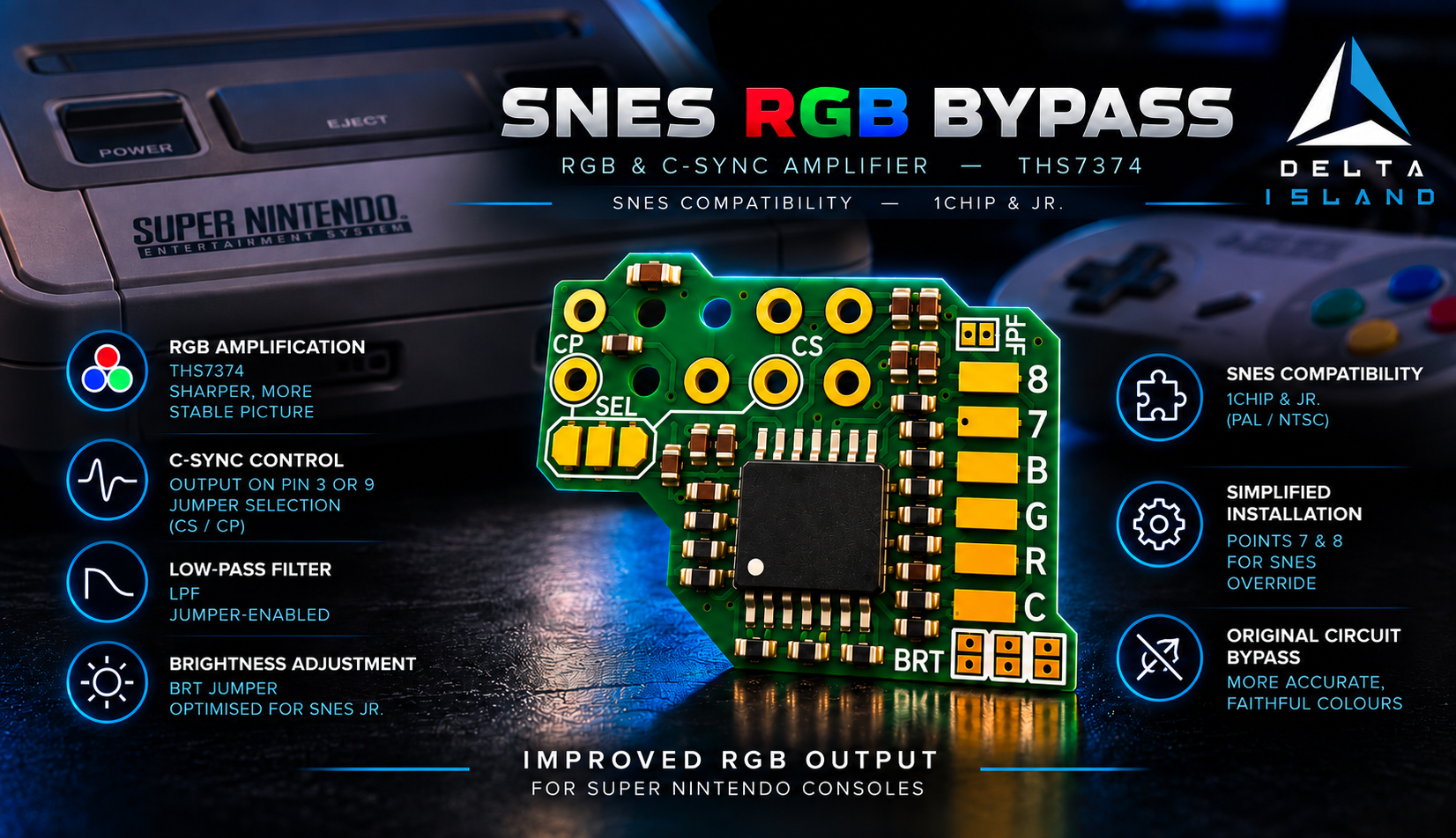
Improve the RGB output of your SNES / Super Famicom 1CHIP or restore RGB on your SNES2 / Jr. With the Delta SNES RGB Bypass, tailor filtering, brightness and sync to your video setup.
Introduction
Not all Super Nintendo consoles deliver the same picture quality.
Delta SNES RGB Bypass is designed for Super Nintendo / Super Famicom 1CHIP / SNES2 / Jr
Models with a 1CHIP motherboard generally produce a sharper picture than earlier generations. However, their original video circuitry has certain limitations and can still be improved.
Delta SNES RGB Bypass is designed for Super Nintendo / Super Famicom 1CHIP / SNES2 / Jr
Models with a 1CHIP motherboard generally produce a sharper picture than earlier generations. However, their original video circuitry has certain limitations and can still be improved.
The Delta SNES RGB Bypass was developed to improve the RGB signal quality of SNES/SFC 1CHIP and Jr. consoles.
It taps the console’s RGB and C-Sync signals directly, amplifies them and routes them to the Multi-Out video connector.
It taps the console’s RGB and C-Sync signals directly, amplifies them and routes them to the Multi-Out video connector.
Key features:
-
RGB signal amplification.
-
Bypasses the original RGB amplification circuitry.
-
Improved RGB signal quality and sharpness.
-
Restores RGB outputs on SNES Jr. consoles.
-
Pure C-Sync output and C-Sync signal management.
-
Selectable C-Sync output pin: Multi-Out pin 3 or pin 9.
-
Optional low-pass filter (LPF).
-
Brightness correction for SNES Jr. consoles using the BRT jumper.
-
Additional connection points to simplify Delta SNES Override installation.
Required equipment
-
A Delta SNES RGB Bypass.
-
A compatible Super Nintendo.
-
A 4.5 mm Gamebit screwdriver.
-
A Phillips screwdriver.
-
A fine-tip soldering iron.
-
Good-quality solder.
-
Soldering flux.
-
Tweezers.
-
Thin, flexible wire (28 to 32 AWG).
-
Kapton insulating tape.
-
A multimeter.
-
Isopropyl alcohol for cleaning.
-
An RGB cable suited to the console’s configuration.
-
Optional: a hot-air rework station for removing SMD components.
-
Optional: an oscilloscope for checking video signal levels.
Start your installation with the right module.
Find the Delta SNES RGB Bypass on the Delta Store, then follow this guide to configure it for your console and RGB cable.
1. Disassembling your SNES Super Nintendo / Super Famicom
The following videos will guide you step by step through opening and disassembling your console.
Remember to have a 4.5 mm Security Bit (Gamebit) screwdriver ready: it is required to remove the security screws underneath the console.
Remember to have a 4.5 mm Security Bit (Gamebit) screwdriver ready: it is required to remove the security screws underneath the console.
Super Nintendo / Super Famicom disassembly videos
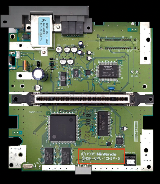
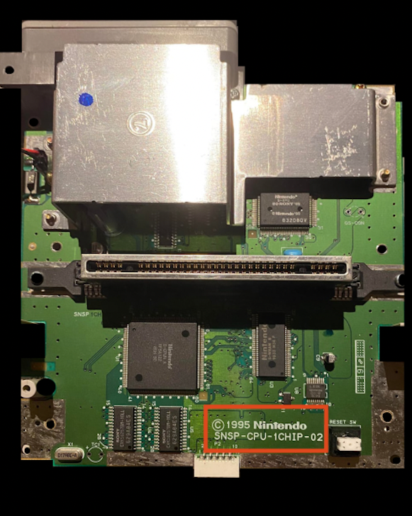
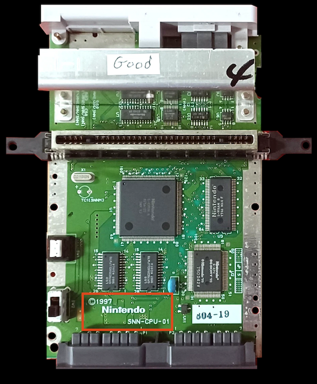
2. Identifying your SNES Super Nintendo / Super Famicom 1CHIP / Jr. motherboard
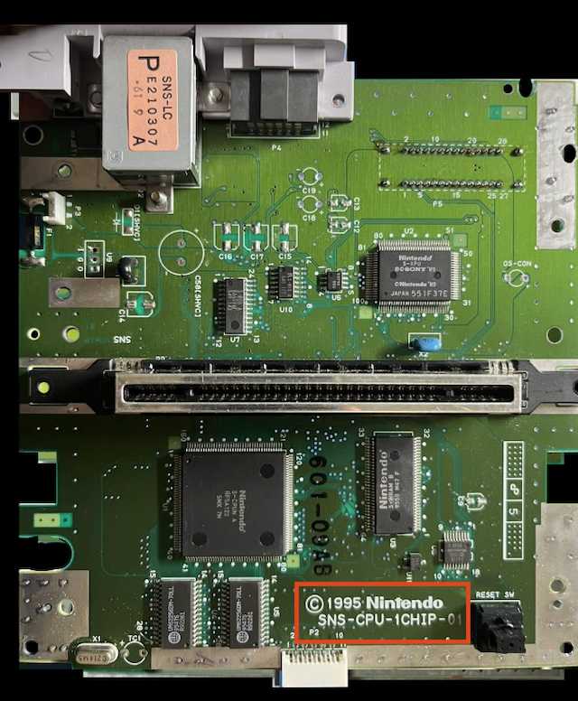
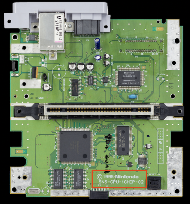
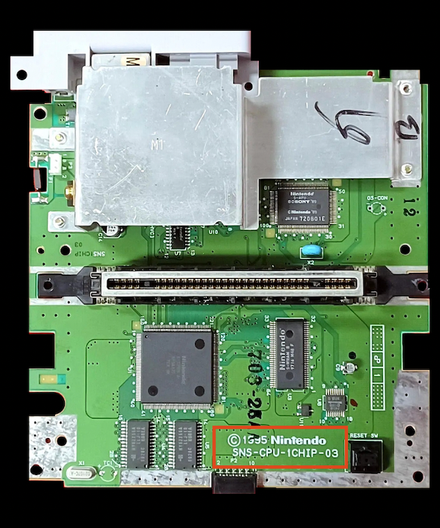
Identify your motherboard using the following photos:

SNS-CPU-1CHIP-01
Super Nintendo / Famicom - NTSC
SNS-CPU-1CHIP-02
Super Nintendo / Famicom - NTSC
SNS-CPU-1CHIP-03
Super Nintendo / Famicom - NTSC
SNSP-CPU-1CHIP-01
Super Nintendo - PAL
SNSP-CPU-1CHIP-02
Super Nintendo - PAL
SNN-CPU-01
Super Nintendo / Famicom Jr - NTSC
3 - Delta SNES RGB Bypass overview and configuration
The Delta SNES RGB Bypass is designed to mount directly onto the Super Nintendo’s Multi-Out video connector.
Its main circuit uses a four-channel video amplifier.
Three channels handle the RGB components, while the fourth handles the C-Sync synchronisation signal.
Its main circuit uses a four-channel video amplifier.
Three channels handle the RGB components, while the fourth handles the C-Sync synchronisation signal.
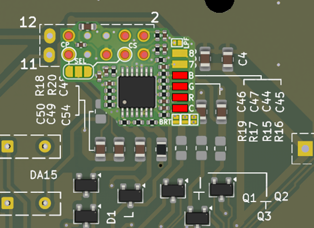
The PCB includes several connection points and jumpers to adapt its operation to the console and the user’s preferences.
3.1 - C-Sync output configuration
The Delta SNES RGB Bypass has a selector for choosing which Multi-Out connector pin carries the C-Sync signal.
Two configurations are available:
Two configurations are available:
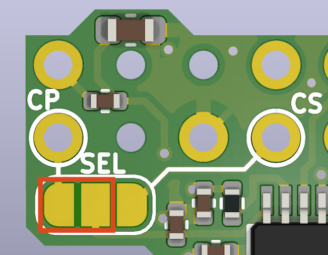
CP configuration
SEL = CP C-Sync OUT -> Multi-Out pin 9
This configuration replaces the composite video signal on Multi-Out pin 9 with the C-Sync signal.
It can be used when you want to carry sync on the line normally reserved for composite video.
The advantage of this configuration is that the RGB cable can be reused without modification.
SEL = CP C-Sync OUT -> Multi-Out pin 9
This configuration replaces the composite video signal on Multi-Out pin 9 with the C-Sync signal.
It can be used when you want to carry sync on the line normally reserved for composite video.
The advantage of this configuration is that the RGB cable can be reused without modification.
Using your soldering iron, bridge the two pads outlined in red in this diagram:
Here is the wiring diagram for a standard NTSC RGB cable compatible with this configuration:

The same diagram, including a 470-ohm resistor on the sync line (required if the picture rolls vertically):
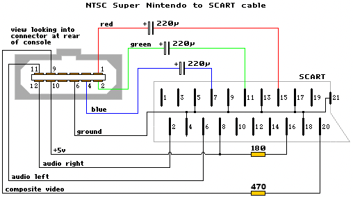
CS configuration:
SEL = CS C-Sync OUT -> Multi-Out pin 3
This configuration routes C-Sync to Multi-Out pin 3.
This is the pin used for C-Sync on some NTSC Super Nintendo consoles.
SEL = CS C-Sync OUT -> Multi-Out pin 3
This configuration routes C-Sync to Multi-Out pin 3.
This is the pin used for C-Sync on some NTSC Super Nintendo consoles.
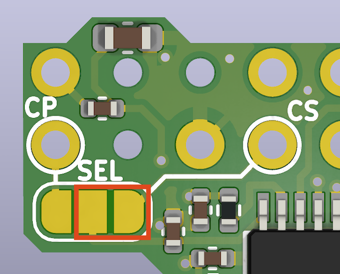
Using your soldering iron, bridge the two pads outlined in red in this diagram:
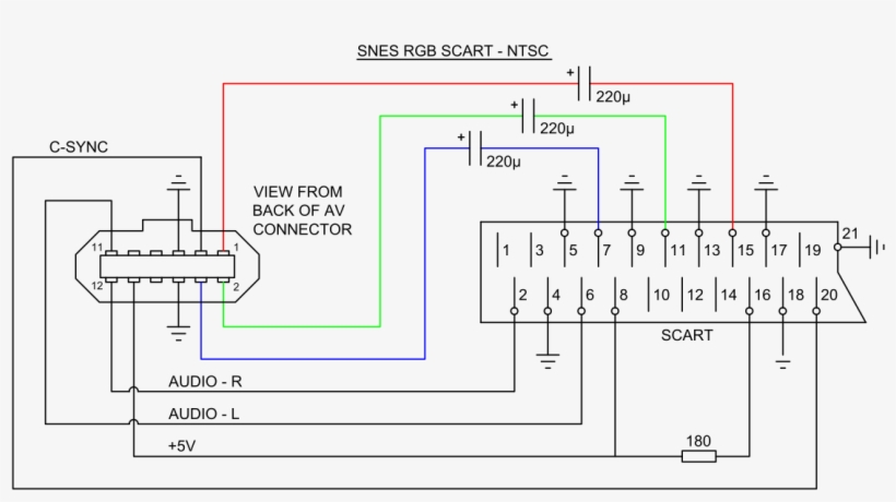
Here is the wiring diagram for a standard NTSC RGB cable compatible with this configuration:
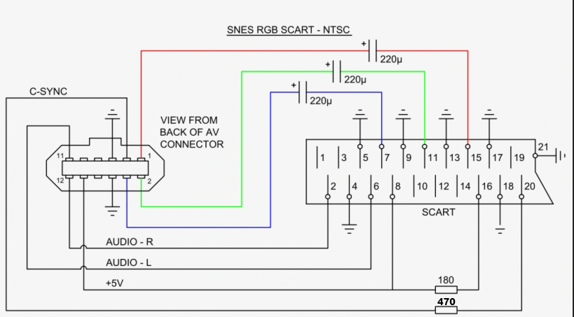
The same diagram, including a 470-ohm resistor on the sync line (required if the picture rolls vertically):
3.2 - Low-Pass Filter
Delta SNES RGB Bypass includes a low-pass filter that attenuates certain high-frequency components of the video signal.
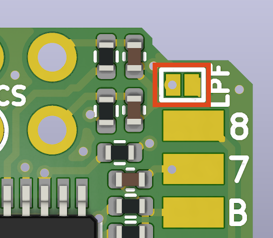
The LPF jumper lets you enable or disable this filter on the Delta SNES RGB Bypass.
The LPF jumper lets you enable or disable this filter on the Delta SNES RGB Bypass.
-
LPF open: Low-pass filter disabled.
-
LPF closed: Low-pass filter enabled.
To enable the low-pass filter, use your soldering iron to bridge the two pads outlined in red in this diagram:
Filter disabled:
Recommended when the console is connected to equipment that already provides its own video filtering.
Filter enabled:
May help reduce certain high-frequency interference when connected directly to a display.
Recommended when the console is connected to equipment that already provides its own video filtering.
Filter enabled:
May help reduce certain high-frequency interference when connected directly to a display.
3.3 - BRT jumper: Brightness
The BRT jumpers adjust the brightness of the video signal.
SNES Jr / SNES2 Mini :
BRT = OPEN
SNES Jr / SNES2 Mini :
BRT = OPEN
SNES 1CHIP :
BRT = CLOSED
Using your soldering iron, make three solder bridges between the pairs of pads outlined in red in this diagram:
BRT = CLOSED
Using your soldering iron, make three solder bridges between the pairs of pads outlined in red in this diagram:
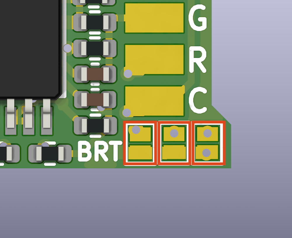
This is particularly important for SNES 1CHIP consoles, whose brightness level requires correction.
3.4 Video inputs and SNES Override connection points
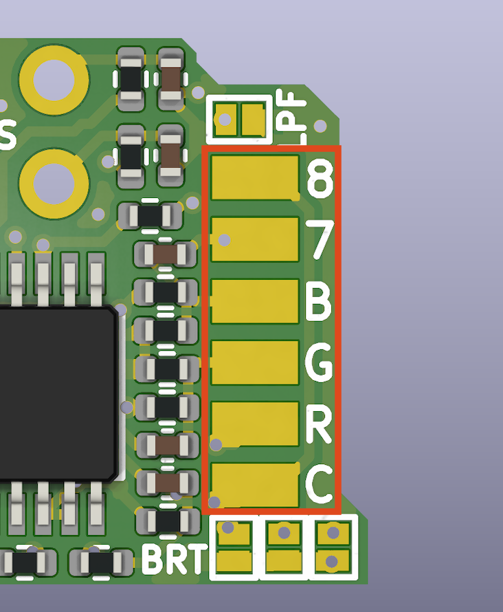
The four video inputs and the two “Delta SNES Override” connection points, 7 and 8, are located on the right-hand side of the PCB.
-
8 : Delta SNES Override point 8
-
7 : Delta SNES Override point 7
-
R : Red video input.
-
G : Green video input.
-
B : Blue video input.
-
C : Composite sync input (C-Sync).
These inputs must be connected to the corresponding signals on the motherboard.
The aim is to tap the video signals before they are processed by the original amplification circuitry.
The PCB also has two additional points labelled 7 and 8 on its right-hand side.
These points were added to simplify integration with the Delta SNES Override.
They simplify the connections between the two modifications when both are installed in the same console.
The aim is to tap the video signals before they are processed by the original amplification circuitry.
The PCB also has two additional points labelled 7 and 8 on its right-hand side.
These points were added to simplify integration with the Delta SNES Override.
They simplify the connections between the two modifications when both are installed in the same console.
Installation with SNES Override:
Points 7 and 8 can be used as shown in the Delta SNES Override installation diagram.
Points 7 and 8 can be used as shown in the Delta SNES Override installation diagram.
For more information about “Delta SNES Override”, the complete tutorial is available here:
TUTORIAL - SNES OVERRIDE – Take full control of your Super Nintendo / Famicom
TUTORIAL - SNES OVERRIDE – Take full control of your Super Nintendo / Famicom
4 - Installing the Delta SNES RGB Bypass
4.1 - Delta SNES RGB Bypass – SNS-CPU-1CHIP-01 / -02 / -03 motherboards (NTSC)
4.1.1 - Preparing SNS-CPU-1CHIP-01 / -02 / -03 motherboards
The original RGB signals must be isolated before installing the Delta SNES RGB Bypass.
R15, R16 and R17 - Remove these three resistors outlined in purple to isolate the console’s original RGB signals.
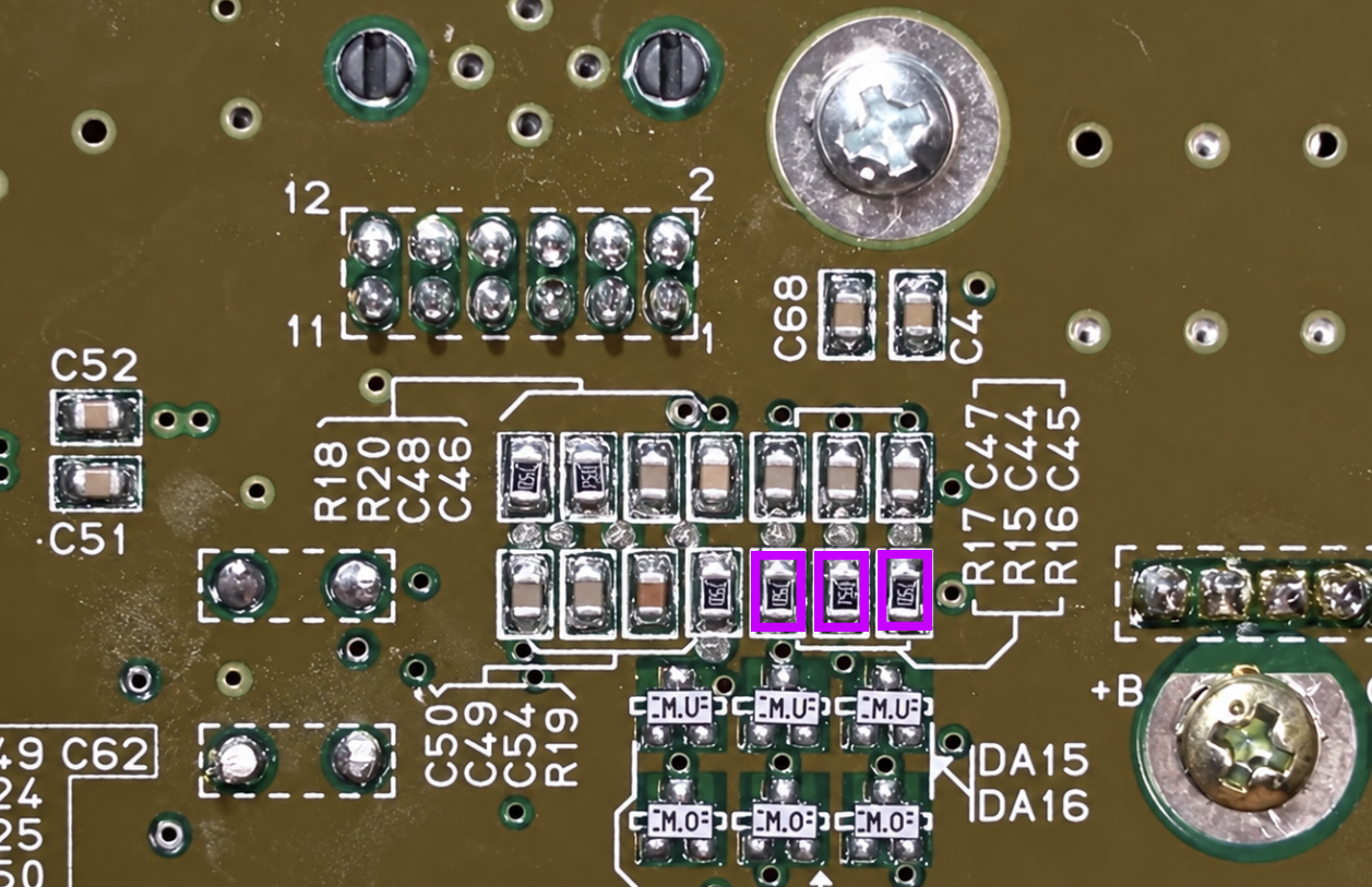
On SNS-CPU-1CHIP-01 and SNS-CPU-1CHIP-02 revisions, the original C-Sync signal is already connected to pin 3 of the Multi-Out connector.
Although this signal can be retained, this configuration is not recommended when installing the Delta SNES RGB Bypass.
To isolate the original signals and allow them to be replaced by those generated by the Delta SNES RGB Bypass, make the following modifications:
Although this signal can be retained, this configuration is not recommended when installing the Delta SNES RGB Bypass.
To isolate the original signals and allow them to be replaced by those generated by the Delta SNES RGB Bypass, make the following modifications:
R12 - Remove this resistor to disconnect the original C-Sync signal from Multi-Out pin 3.
The SNS-CPU-1CHIP-03 revision does not have an original C-Sync signal connected to the Multi-Out connector.
No modification to the C-Sync line is therefore required on SNS-CPU-1CHIP-03.
The SNS-CPU-1CHIP-03 revision does not have an original C-Sync signal connected to the Multi-Out connector.
No modification to the C-Sync line is therefore required on SNS-CPU-1CHIP-03.
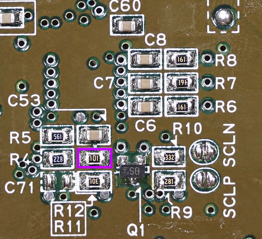
Important:
Before continuing with the installation, make sure the relevant resistors have been removed and that no solder bridges remain between their pads.
This preparation prevents conflicts between the original video signals and those supplied by the Delta SNES RGB Bypass.
Before continuing with the installation, make sure the relevant resistors have been removed and that no solder bridges remain between their pads.
This preparation prevents conflicts between the original video signals and those supplied by the Delta SNES RGB Bypass.
4.1.2 - C-Sync output configuration
Using pin 9 (composite video output)
If you want to use Multi-Out pin 9, normally dedicated to the composite video signal (CVBS), to carry the C_SYNC signal to your television, an additional modification is required.
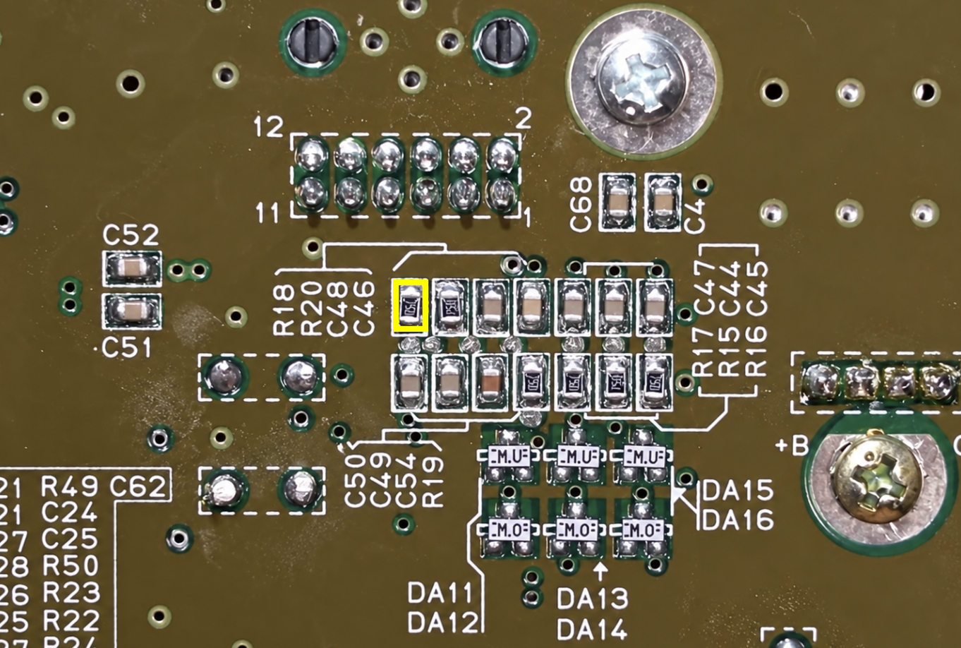
You must remove resistor R18 from the motherboard to isolate the original composite video output.
Once this resistor has been removed, the Delta SNES RGB Bypass C_SYNC signal can be configured in “CP” mode to output on Multi-Out pin 9, replacing the composite signal.
For more information about the different wiring options and the precautions to follow, see section “3.1 - C-Sync output configuration”.
If you want to use Multi-Out pin 9, normally dedicated to the composite video signal (CVBS), to carry the C_SYNC signal to your television, an additional modification is required.
You must remove resistor R18 from the motherboard to isolate the original composite video output.
Once this resistor has been removed, the Delta SNES RGB Bypass C_SYNC signal can be configured in “CP” mode to output on Multi-Out pin 9, replacing the composite signal.
For more information about the different wiring options and the precautions to follow, see section “3.1 - C-Sync output configuration”.
Remove resistor R18, outlined in yellow, to configure the C-Sync output in “CP” mode
For more information about the different wiring options and the precautions to follow, see section “3.1 - C-Sync output configuration”.
4.1.3 - Installing the Delta SNES RGB Bypass
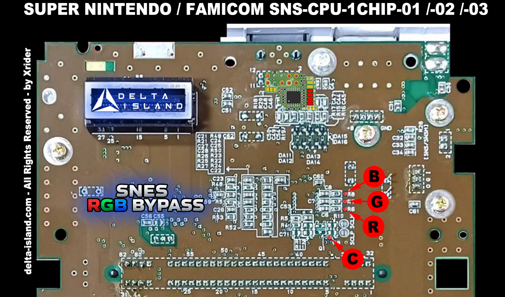
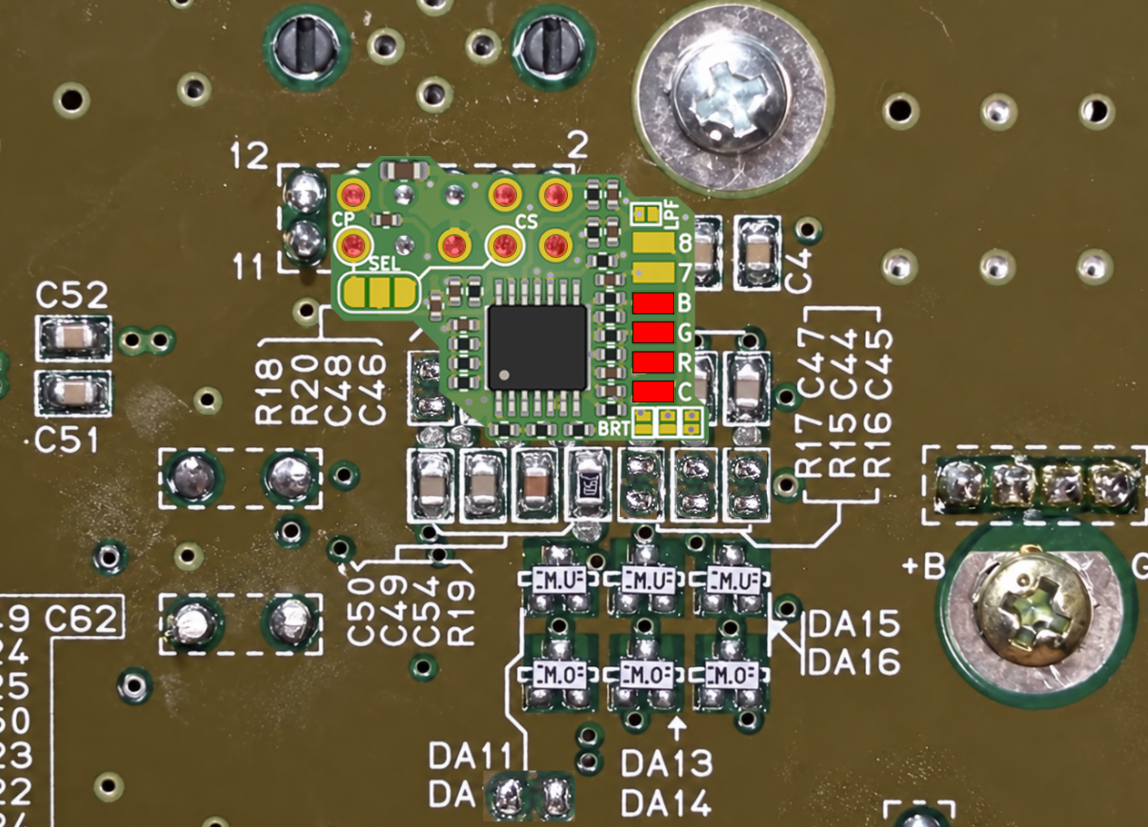
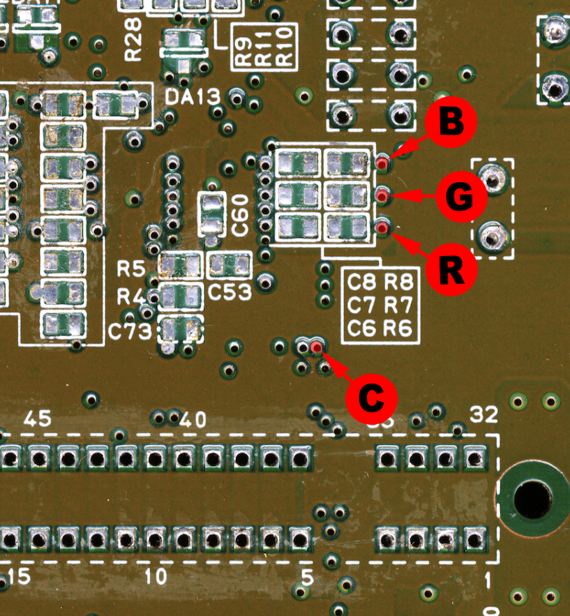
Position the Delta SNES RGB Bypass and solder it as shown in the following diagrams:
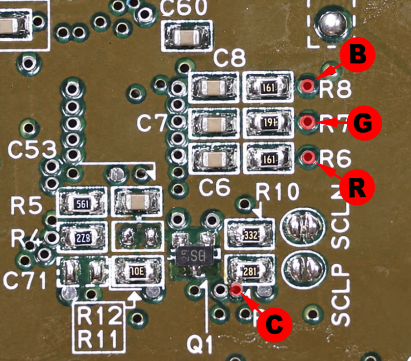
4.2 - Delta SNES RGB Bypass - SNSP-CPU-1CHIP-01 / -02 motherboards (PAL)
4.2.1 - Preparing SNSP-CPU-1CHIP-01 / -02 motherboards (PAL)
On PAL Super Nintendo consoles, a +12 V supply is present on pin 3 of the Multi-Out connector.
The +12 V on Multi-Out pin 3 is incompatible with the Delta SNES RGB Bypass C-Sync output.
When installing the Delta SNES RGB Bypass, this pin must be freed up so it can be used to output the composite sync signal (C-Sync).
The console’s original RGB signals must also be isolated so they can be replaced by those supplied by the Delta SNES RGB Bypass.
The +12 V on Multi-Out pin 3 is incompatible with the Delta SNES RGB Bypass C-Sync output.
When installing the Delta SNES RGB Bypass, this pin must be freed up so it can be used to output the composite sync signal (C-Sync).
The console’s original RGB signals must also be isolated so they can be replaced by those supplied by the Delta SNES RGB Bypass.
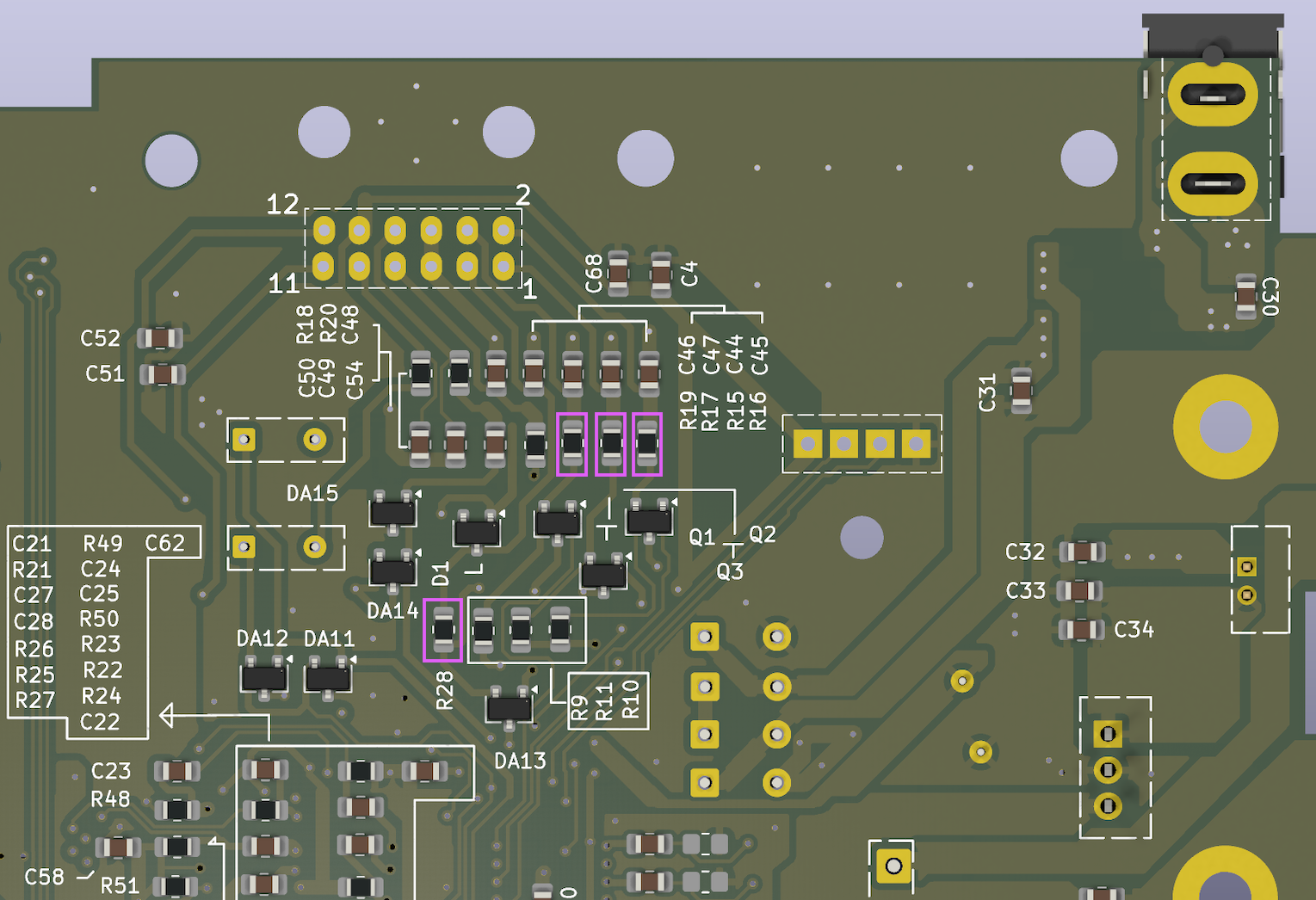
To do this, remove the resistors outlined in purple:
R28 - Remove this resistor to disconnect the +12 V supply from pin 3 of the Multi-Out connector.
R15, R16 and R17 - Remove these three resistors to isolate the console’s original RGB signals.
R15, R16 and R17 - Remove these three resistors to isolate the console’s original RGB signals.
Important:
Before continuing with the installation, make sure all the relevant resistors have been removed and that no solder bridges remain between their pads.
These modifications isolate the original video circuitry and prevent electrical conflicts with the signals generated by the Delta SNES RGB Bypass.
Before continuing with the installation, make sure all the relevant resistors have been removed and that no solder bridges remain between their pads.
These modifications isolate the original video circuitry and prevent electrical conflicts with the signals generated by the Delta SNES RGB Bypass.
4.2.2 - C-Sync output configuration
Using pin 9 (composite video output)
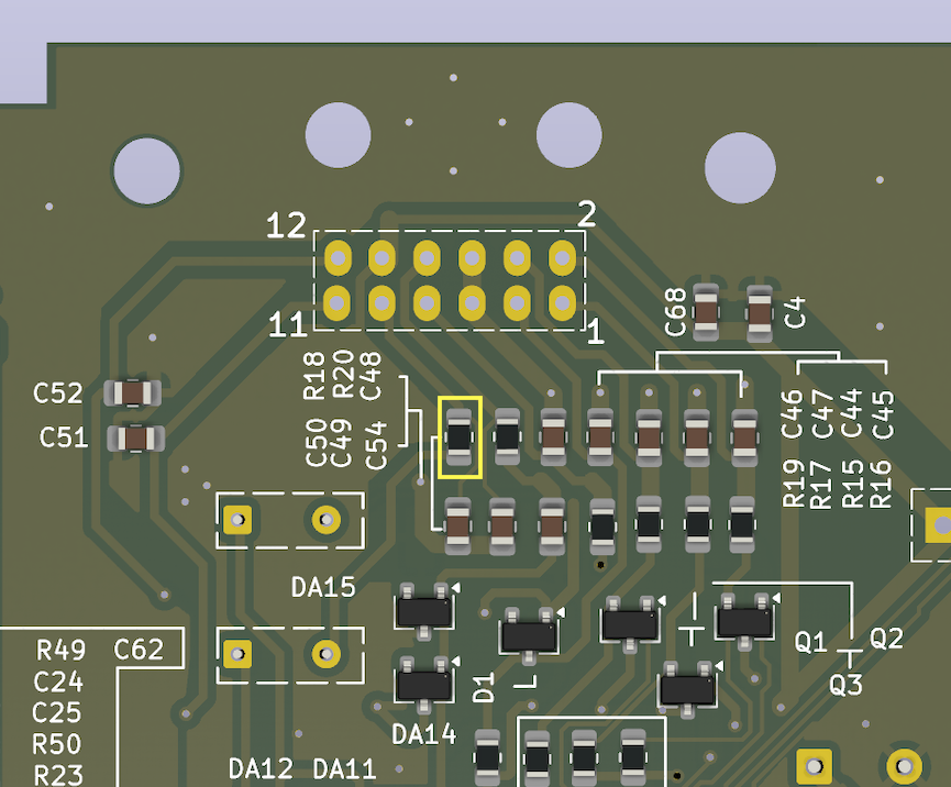
If you want to use Multi-Out pin 9, normally dedicated to the composite video signal (CVBS), to carry the C_SYNC signal to your television, an additional modification is required.
You must remove resistor R18 from the motherboard to isolate the original composite video output.
Once this resistor has been removed, the Delta SNES RGB Bypass C_SYNC signal can be configured in “CP” mode to output on Multi-Out pin 9, replacing the composite signal.
For more information about the different wiring options and the precautions to follow, see section “3.1 - C-Sync output configuration”.
If you want to use Multi-Out pin 9, normally dedicated to the composite video signal (CVBS), to carry the C_SYNC signal to your television, an additional modification is required.
You must remove resistor R18 from the motherboard to isolate the original composite video output.
Once this resistor has been removed, the Delta SNES RGB Bypass C_SYNC signal can be configured in “CP” mode to output on Multi-Out pin 9, replacing the composite signal.
For more information about the different wiring options and the precautions to follow, see section “3.1 - C-Sync output configuration”.
Remove resistor R18, outlined in yellow, to configure the C-Sync output in “CP” mode
For more information about the different wiring options and the precautions to follow, see section “3.1 - C-Sync output configuration”.
4.2.3 - Installing the Delta SNES RGB Bypass
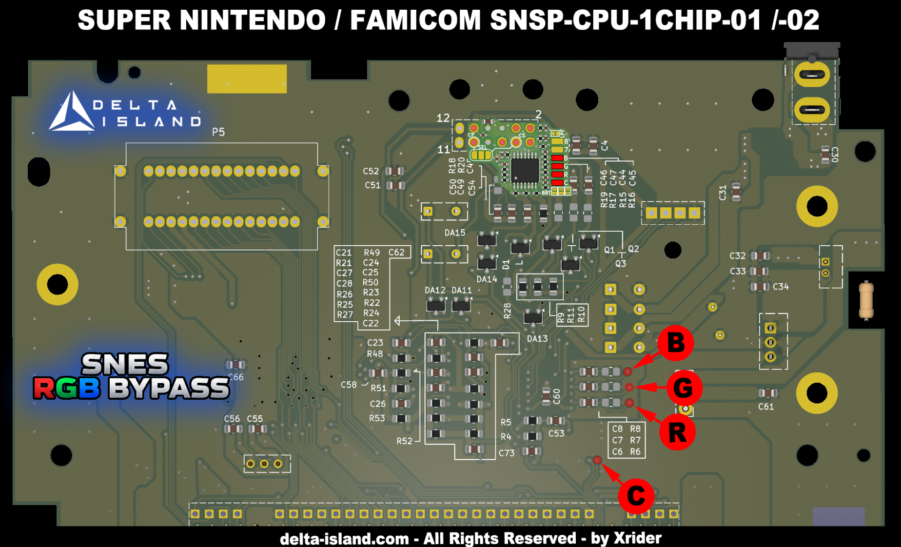
Position the Delta SNES RGB Bypass and solder it as shown in the following diagrams:
For reference, the photo shows a motherboard with all its components removed, for illustration purposes only. Your motherboard must retain its original components.
4.3 - Delta SNES RGB Bypass - SNN-CPU-01 motherboard (SNES/SFC Jr.)
4.3.1 - Preparing the SNN-CPU-01 motherboard
Unlike standard Super Nintendo consoles, SNES Jr. consoles do not have RGB outputs wired to their Multi-Out connector from the factory.
However, the RGB signals are available on the console’s video chip.
The Delta SNES RGB Bypass taps these signals to restore a complete RGB output.
However, the RGB signals are available on the console’s video chip.
The Delta SNES RGB Bypass taps these signals to restore a complete RGB output.
4.3.2 - C-Sync output configuration
On the SNES Jr., Multi-Out pin 3 is unused. The Delta SNES RGB Bypass C_SYNC output can therefore be connected directly to it without any prior motherboard modification.
This configuration allows you to use an RGB cable compatible with C-Sync on pin 3.
Using pin 9 (composite video output)
If you want to use Multi-Out pin 9, normally dedicated to the composite video signal (CVBS), to carry the C_SYNC signal to your television, an additional modification is required.
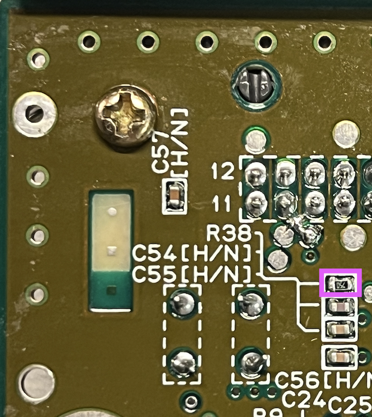
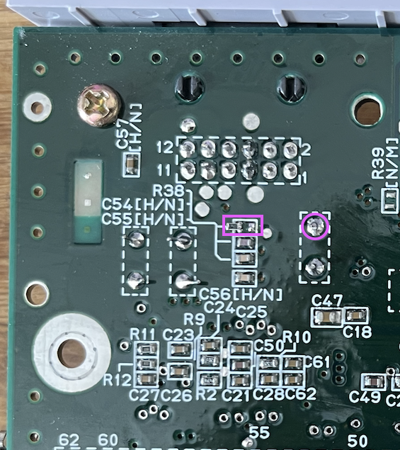
You must remove resistor R38 from the motherboard to isolate the original composite video output.
Once this resistor has been removed, the Delta SNES RGB Bypass C_SYNC signal can be configured in “CP” mode to output on Multi-Out pin 9, replacing the composite signal.
For more information about the different wiring options and the precautions to follow, see section “3.1 - C-Sync output configuration”.
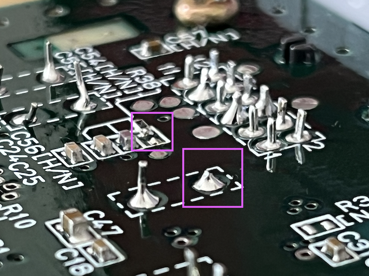
You must also trim the through-hole capacitor lead flush with the motherboard if this component is present (Famicom Jr.).
This configuration allows you to use an RGB cable compatible with C-Sync on pin 3.
Using pin 9 (composite video output)
If you want to use Multi-Out pin 9, normally dedicated to the composite video signal (CVBS), to carry the C_SYNC signal to your television, an additional modification is required.
You must remove resistor R38 from the motherboard to isolate the original composite video output.
Once this resistor has been removed, the Delta SNES RGB Bypass C_SYNC signal can be configured in “CP” mode to output on Multi-Out pin 9, replacing the composite signal.
For more information about the different wiring options and the precautions to follow, see section “3.1 - C-Sync output configuration”.
You must also trim the through-hole capacitor lead flush with the motherboard if this component is present (Famicom Jr.).
Remove resistor R38, outlined in purple, to configure the C-Sync output in “CP” mode
Trim the lead of through-hole capacitor C52 flush with the motherboard, if present
Trim the lead of through-hole capacitor C52 flush with the motherboard, if present
For more information about the different wiring options and the precautions to follow, see section “3.1 - C-Sync output configuration”.
4.3.3 - Installing the Delta SNES RGB Bypass
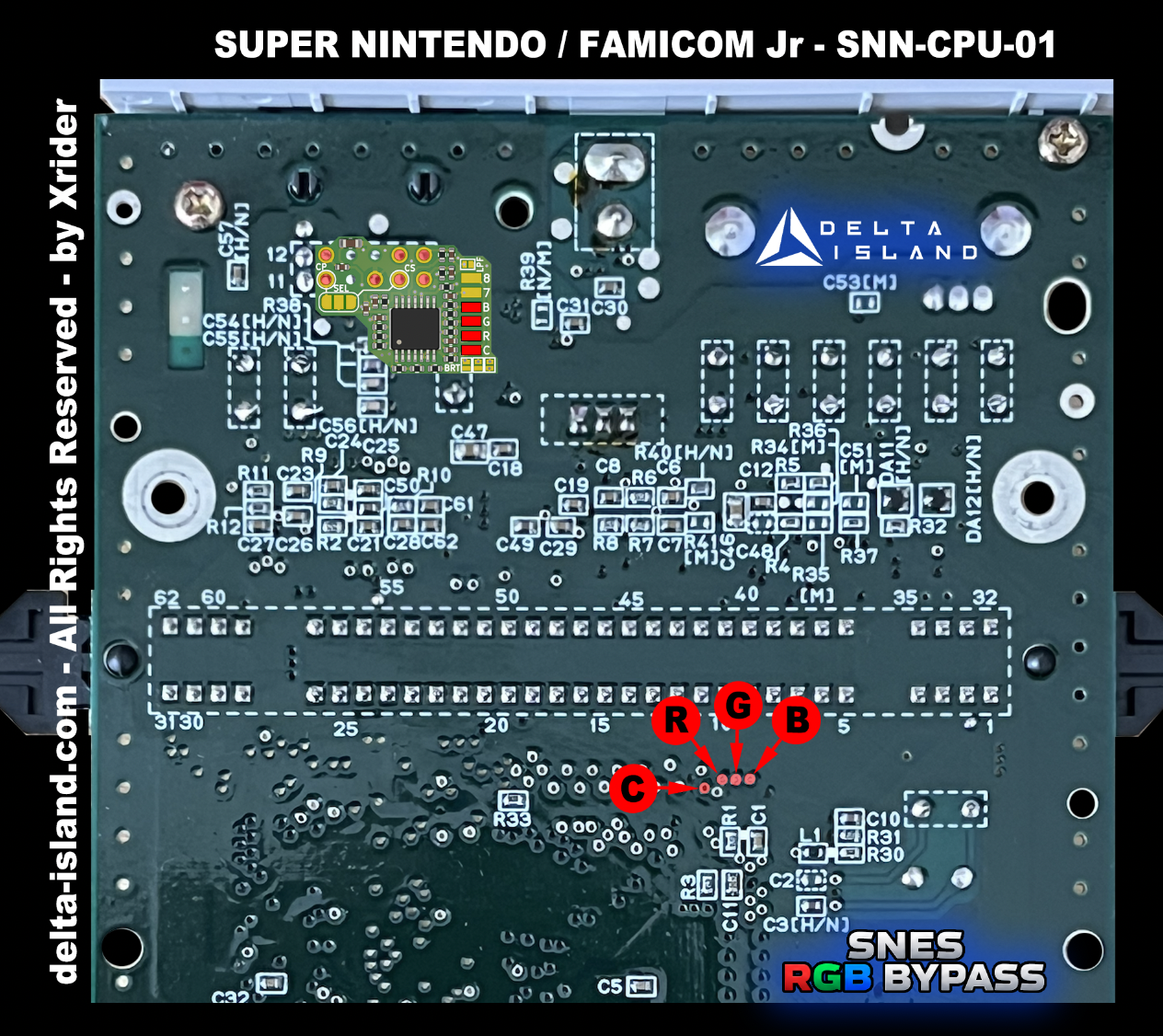
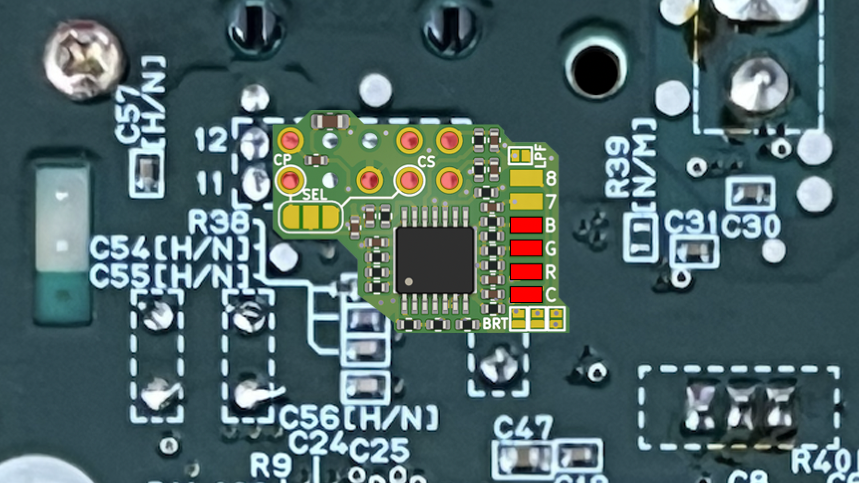
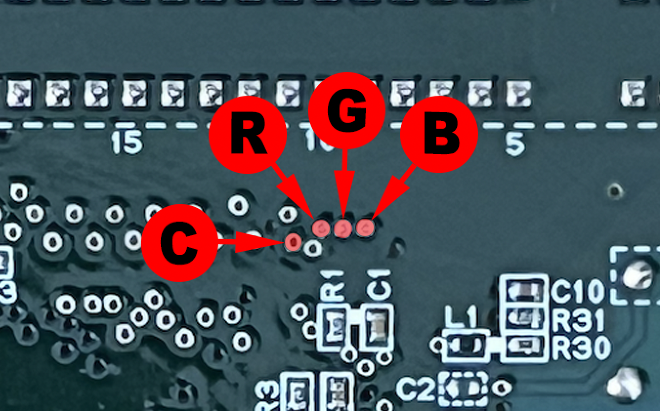
Position the Delta SNES RGB Bypass and solder it as shown in the following diagrams:
5 - FAQ: Frequently asked questions and troubleshooting
Q: Can I use the original RGB cable from my PAL Super Nintendo?
No, the original PAL Super Nintendo RGB cable is not compatible with the Delta SNES RGB Bypass.
You must use a suitable RGB cable with the following specifications:
No, the original PAL Super Nintendo RGB cable is not compatible with the Delta SNES RGB Bypass.
You must use a suitable RGB cable with the following specifications:
-
RGB lines: each R, G and B line must have a 220 µF electrolytic capacitor connected in series, with its positive (+) terminal facing the console.
-
Synchronisation (C-Sync): the Delta SNES RGB Bypass outputs a TTL-level C-Sync signal directly on the console’s MultiOut port. The cable must therefore include a 470 Ω resistor in series on the sync line to adapt the signal for consumer equipment (televisions, OSSC, Framemeister, etc.).
Q: My Super Nintendo powers on, but I have no picture. What should I do?
Start by checking the following:
Start by checking the following:
-
The Delta SNES RGB Bypass +5 V supply.
-
The ground connection (GND).
-
The RGB input connections (R, G and B).
-
The C-Sync signal connection (C).
-
The SEL jumper setting (CS or CP).
-
RGB cable compatibility and wiring.
Also check that there are no short circuits or solder bridges on the PCB or Multi-Out connector.
Q: My picture rolls vertically, jumps or regularly loses sync. Why?
This usually indicates a video sync problem.
Check the C-Sync signal connection and the SEL jumper setting:
This usually indicates a video sync problem.
Check the C-Sync signal connection and the SEL jumper setting:
-
SEL set to CS: C-Sync routed to Multi-Out pin 3.
-
SEL set to CP: C-Sync routed to Multi-Out pin 9.
Also make sure the original signal on the selected pin has been isolated and that your RGB cable uses the correct sync line.
A C-Sync level unsuitable for your video equipment can also cause this type of problem.
Use a suitable cable with a 470 Ω resistor on the sync line (C-SYNC) for use with most consumer equipment (televisions, OSSC, Framemeister, etc.)!
A C-Sync level unsuitable for your video equipment can also cause this type of problem.
Use a suitable cable with a 470 Ω resistor on the sync line (C-SYNC) for use with most consumer equipment (televisions, OSSC, Framemeister, etc.)!
Q: My SNES picture is far too bright. How can I fix it?
On SNES Jr. consoles, the BRT jumper must be open to reduce brightness.
On other 1CHIP models, check the Delta SNES RGB Bypass input resistor configuration and the RGB cable’s signal adaptation.
Excessive brightness can also result from an RGB signal level that is too high.
On SNES Jr. consoles, the BRT jumper must be open to reduce brightness.
On other 1CHIP models, check the Delta SNES RGB Bypass input resistor configuration and the RGB cable’s signal adaptation.
Excessive brightness can also result from an RGB signal level that is too high.
Q: My picture is too dark. What could cause this?
Several factors may be responsible:
Several factors may be responsible:
-
An incorrect BRT jumper configuration.
-
Resistor values unsuitable for your SNES revision.
-
An RGB cable containing unsuitable components.
-
A poor connection on one of the RGB inputs.
Also check the settings on your television or video converter.
Q: A colour is missing from the picture (red, green or blue). What should I check?
A missing colour usually indicates a problem with the corresponding RGB line.
Check:
A missing colour usually indicates a problem with the corresponding RGB line.
Check:
-
The wire connecting the motherboard to the Delta SNES RGB Bypass R, G or B input.
-
The solder joints on the PCB.
-
Electrical continuity to the Multi-Out connector.
-
The absence of short circuits between the RGB lines.
Also check that the components removed from the motherboard match your SNES revision.
Q: I can see shadows or doubled edges around some objects. Is this normal?
This effect is known as Ghosting.
It can occur on some Super Nintendo 1CHIP consoles, independently of the Delta SNES RGB Bypass installation.
One known fix is to replace motherboard capacitor C11 with a 470 nF ceramic capacitor, after checking the relevant revision.
Before making any changes, check whether the problem occurs with several games and different display devices.
This effect is known as Ghosting.
It can occur on some Super Nintendo 1CHIP consoles, independently of the Delta SNES RGB Bypass installation.
One known fix is to replace motherboard capacitor C11 with a 470 nF ceramic capacitor, after checking the relevant revision.
Before making any changes, check whether the problem occurs with several games and different display devices.
Q: My picture has noise or interference. How can I improve the signal quality?
Start by checking:
Start by checking:
-
The quality of the ground connections.
-
The length of the wires connecting the motherboard to the Delta SNES RGB Bypass.
-
Wire routing near digital circuitry.
-
The quality of the RGB cable.
-
The absence of faulty solder joints.
You can also try enabling the low-pass filter built into the THS7374.
To do this, close the LPF jumper on the Delta SNES RGB Bypass.
This filter attenuates certain high-frequency components of the video signal.
To do this, close the LPF jumper on the Delta SNES RGB Bypass.
This filter attenuates certain high-frequency components of the video signal.
Q: Do I have to enable the LPF filter?
No, enabling it is optional.
No, enabling it is optional.
-
LPF open: Filter disabled.
-
LPF closed: Filter enabled.
We recommend starting with the filter disabled, then comparing the results with your video setup.
Some modern devices already have their own filtering system.
Some modern devices already have their own filtering system.
Q: Can I use the Delta SNES RGB Bypass without installing the Delta SNES Override?
Yes, absolutely!
The Delta SNES RGB Bypass operates completely independently.
Points 7 and 8 on the PCB are only there to simplify Delta SNES Override installation.
If your console does not have SNES Override, simply leave these two points unconnected.
Yes, absolutely!
The Delta SNES RGB Bypass operates completely independently.
Points 7 and 8 on the PCB are only there to simplify Delta SNES Override installation.
If your console does not have SNES Override, simply leave these two points unconnected.
Q: Can I use any RGB cable with the Delta SNES RGB Bypass?
No, it is important to use an RGB cable suited to your console’s configuration.
PAL and NTSC RGB cables may differ in their wiring and internal components.
No, it is important to use an RGB cable suited to your console’s configuration.
PAL and NTSC RGB cables may differ in their wiring and internal components.
In particular, check:
-
The pin used for sync (3 or 9).
-
The presence of any capacitors on the RGB lines.
-
C-Sync signal level adaptation.
-
Compatibility with your television or video converter.
6 - Finishing up
Once operation has been verified:
-
Clean off flux residue with isopropyl alcohol.
-
Check the solder joints one last time.
-
Secure the wires to prevent mechanical strain.
-
Make sure the PCB is properly insulated.
-
Refit the metal shields.
-
Check that nothing is pressing against the Delta SNES RGB Bypass.
-
Close the console.
-
Carry out one final full test.
Your Super Nintendo is now equipped with the Delta SNES RGB Bypass !
You can now enjoy improved RGB output, with filtering, brightness and sync settings to suit your setup.
You can now enjoy improved RGB output, with filtering, brightness and sync settings to suit your setup.
Credits and acknowledgements
The Delta SNES RGB Bypass is based on the open-source work of TzorriMahm and borti4938.
Original project:
TzorriMahm – SNES RGB Bypass Amp
Reference project:
borti4938 – SNES RGB Bypass
Original project:
TzorriMahm – SNES RGB Bypass Amp
Reference project:
borti4938 – SNES RGB Bypass